Greetings.
I have gone as far as I can on the Capacitive Touch Switch Morse Code Keyer.
Now that I am starting a new job I will have financial resources to buy parts to make the first Prototype.
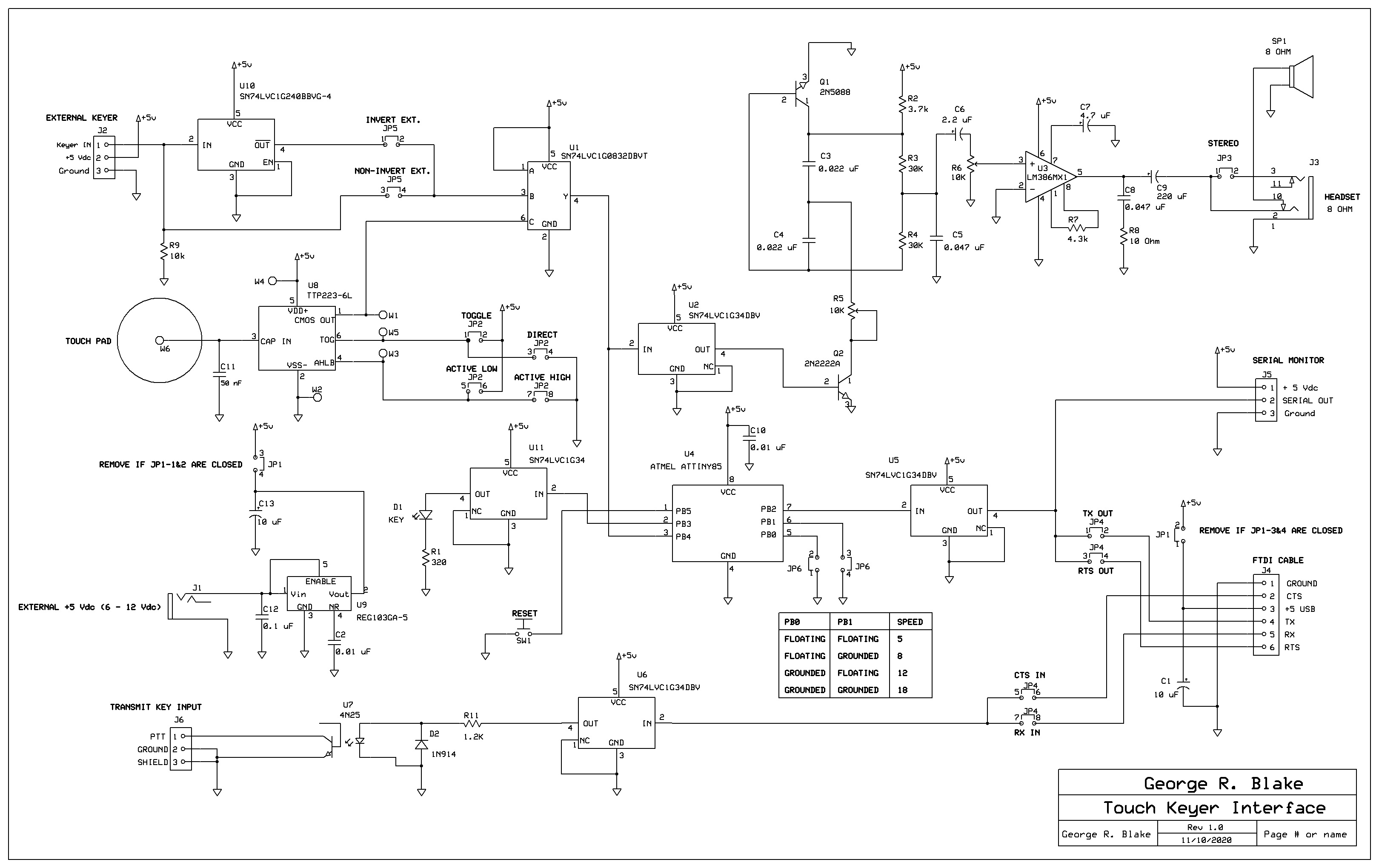
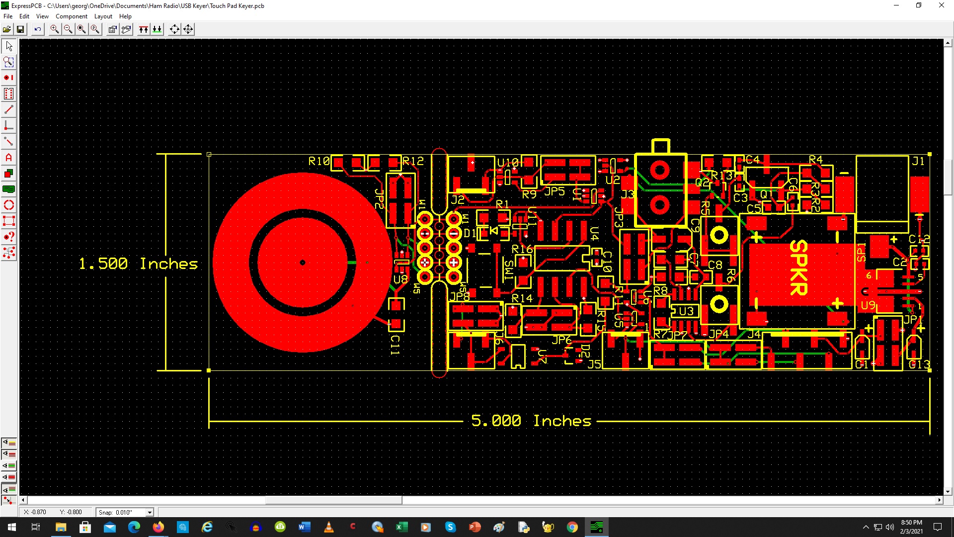
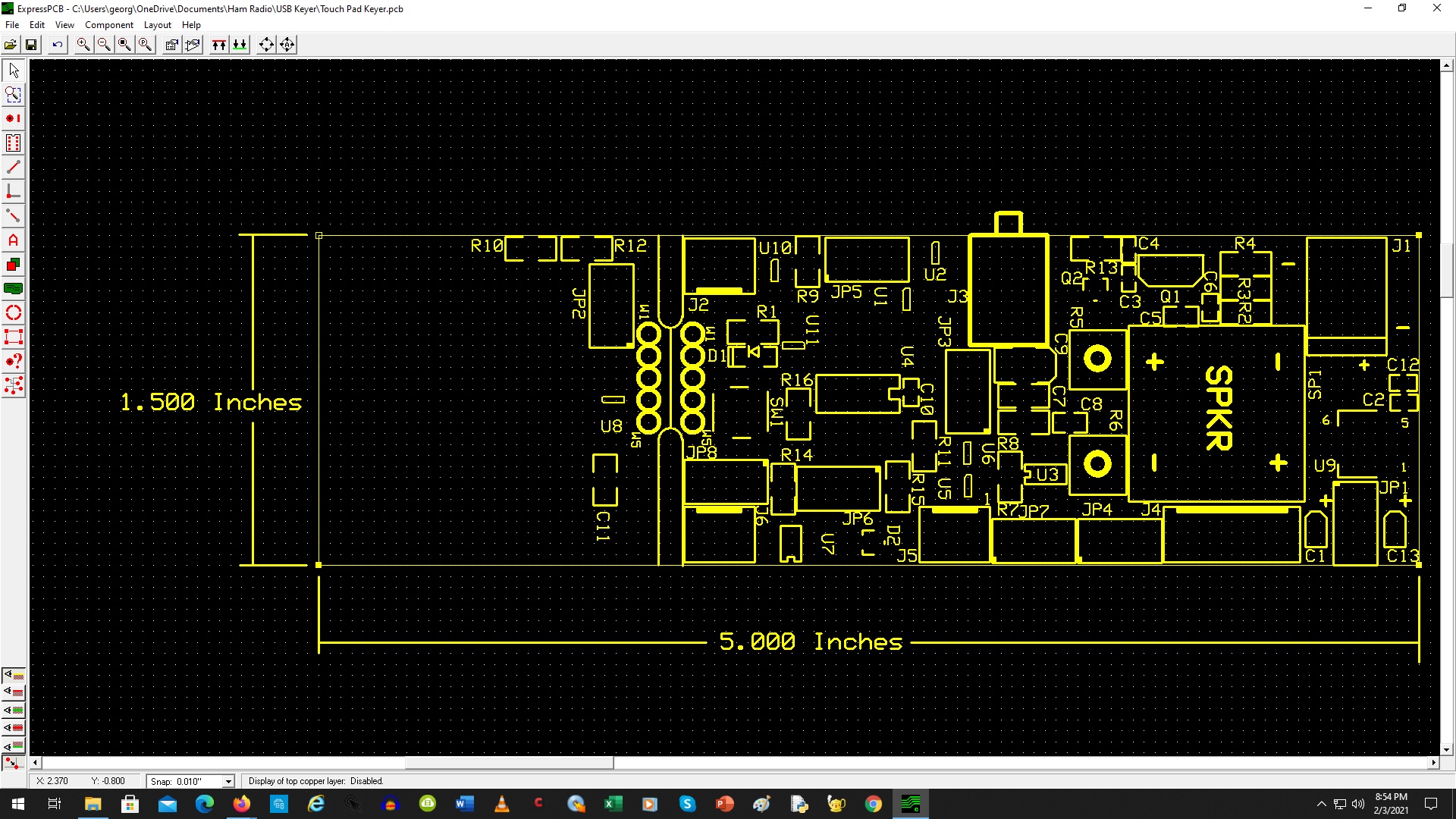
I have attached files of the schematic and layout.
Regards,
George Blake
Capacitive Touch Switch Morse Code Keyer
Description
The Capacitive Touch Switch Morse Code Keyer (aka USB Keyer) is a combination of circuits I have researched on the Internet. I wanted a single-key Keyer for practice and integration into my future Ham Radio station. This is the culmination of the first version. I am sure there will be other iterations later.
I did not want the typical electro-mechanical Keyer as it seemed physically restrictive. I wanted something to tap on to make my Morse Code. I came upon Touch Capacitive Switches that the Arduino community uses. I decided to adapt this into a practice Keyer. I found many IAMBIC / Side Keyer units that people had made, but none with a single straight Keyer. The Capacitive Switch is based on the TTP-223 that most Touch Switches utilize.
I desired an interface to make Morse Code more interesting and allow for future expansion. I came across several articles regarding the AtMel ATTiny85 Arduino CPU. This is a circuit that reads your Morse Code, deciphers it, and then outputs what it “thinks” you sent as a flashing light, Buzzer signal and outputs to a 4x20 character display.
I then came across articles regarding interfacing to a Computer and users who send Morse Code via Computer. Many of the interfaces are via USB. So, more modifications.
The ATTiny85 interfaces utilized a buzzer for sound reproduction and used an output pin directly. I preferred to use something I could vary in pitch and volume. So, another addition. Headphones being an option for quiet coding.
The input into a Transmitter Key input needed to be flexible because of both older and newer grounding techniques. To help prevent problems the interface is Opto-Coupled, and the grounds can be configured.
The power input is also flexible. You can either utilize USB power to drive the unit, or you can connect externally via a wall power supply (Wall Wart) or 9 Volt Battery. 6-12 Vdc is do-able.
There is also an option use your own Key externally instead of the Capacitive Switch.
There are many Buffer-Drivers on board to prevent overloading the ATTiny85 and other circuits.
OPERATION
6-12 Vdc power enters via J1 (External) or via the USB port at J4. Jumpers JP1 select which one is sourced. WARNING: DO NOT CLOSE both jumpers at the same time. JP1-1&2 is closed for USB power, JP1-3&4 is closed for EXTERNAL power. Closing BOTH can cause damage to the Voltage Regulator (U9) and/or your PC. It is ADVISABLE to purchase a FTDI USB-to-RS232 Cable from Sparkfun:
https://www.sparkfun.com/products/9718
This cable is pre-configured with VBUS pass-thru. If the USB is USB 3.0 it is NOT advisable to use the USB as thew voltage may only by +3.3 Vdc.
The Keyer operates via the large 1.25-inch capacitive Touch pad (W6) at the front of the board. The pad creates a capacitive field. When you touch it, capacitor C11 activates U8 (TTP223). This is a capacitive switch IC. The output can be configured for Logic 1 HIGH or LOW, depending on the requirements of your Transmitter keying. JP2 selects this. Optionally you can use an external Key through J2 and select the sense at JP5.
NOTE: The ATTiny85 (U4) requires an active LOW (0 Vdc) to know you pressed the Key.
The PCB is etched / notched so that you can choose to separate the Key from the main board. This may be desired for room, mounting, comfort, etc. Terminals W1-W5 can have pins inserted and you can add a cable between points.
The output of U1 drives both the Code Oscillator and the ATTiny85. A jumper JP3-3&4 will also send the Keyer direct to the Transmitter (J6) if you don’t want to use the USB from a Computer.
The Oscillator circuit is a traditional Morse Code practice Trainer circuit. This controls a RC network Oscillator. PITCH is controlled via R5. The output is driven by U3 up to 12 watts. The output VOLUME is controlled by R6. This drives the speaker (SP1) or optionally a headset plugged into J3. When you plug in to J3, this disables the Speaker. Jumper JP3-1&2 allows you to separate the output for Monoraul use.
The ATTiny85 CPU monitors the Key and deciphers your Morse Code depending on your speed. The SPEED is selected via jumpers JP6.
NOTE: If you change speed with the power ON, you will have to activate the RESET button (SW1).
The ATTiny85 interprets what it sees based on the speed and sends out a Serial data stream. The data is sent to a Monitor output for display on a (typically) 4x20 character LCD display module. You need to have a SERIAL Rx input, NOT I2C.
https://moderndevice.com/product/smdlcd117-bundle/
Conversely, you can use the ATTiny85 to read what is being sent to your Transmitter from your Computer. To do this, short jumper JP3-3&4. This allows the Computer output to be fed back into the ATTiny85 which should, in turn, read it the same as reading the Key. This will then be read and sent to the Monitor. This will also operate the Oscillator. The Oscillator cannot be disabled, but you can turn the VOLUME control (R6) to Minimum.
The output to the FTDI USB cable is 0 / 5 Vdc TTL. This feeds into either: 1. Tx, or 2. CTS, or 3. Both depending on which one you desire to use. Some people have software that utilizes Transmit (Tx), some use Request To Send (RTS).
NOTE: This PCB is NOT supplied with ANY software. Drivers for USB connectivity, Morse Code communications, etc. This is entirely up to the User.
FTDI USB Drivers for Windows, Linux, AppleOS, etc. can typically be found here:
The Morse Code data from the Computer enters via J4 on the Receive (Rx) and/or Clear To Send (CTS) lines, depending on your software. This is directed to the Transmitter Key interface at J6 via Opto-Coupler (U7). This is strictly a switch closure much like a Morse Code Key would be. The Transmitter (typically) sources or sinks current depending on the design and age of the unit. Many Transmitters use +5 Vdc to Ground. Some use the Chassis as the HOT or GROUND. Some use much higher voltages. It is up to the User to determine their requirements. The GROUND and SHIELD lines can be tied to the PCB ground via jumpers JP8.
ATTiny85 C-Code
The PCB comes with the ATTiny85 pre-programmed.
The original code for the ATTiny85 Morse Code Trainer can be found here:
https://github.com/edgar-bonet/tiny-morse-decoder
The ATTiny85 can be programmed using the AVR ATTiny85 USB Programmer:
https://www.sparkfun.com/products/11801